Office Electronics
MAX262 Active Filter Module Programmable Filter High Low Pass Bandpass
$64.99
$64.99
Sale
Unavailable
SKU CJBG1677695
- Delivery
- Quoted for your address at checkout.
- Availability
- Follows the option you select.
- Returns
- Eligibility & instructions →
Features
1. with a filter design software, with a microprocessor interface;
2. can control 64 different center frequency f0, 128 different quality factor Q and 4 kinds of work patterns;
3. the center frequency f0 and quality factor Q can be independently programmed;
4. can provide three clock input (external clock input, RC oscillator and crystal devices);
5. the central frequency f0 range of 1Hz ~ 140kHz, the maximum input clock 4MHz;
6. the filter circuit structure is simple, less external components, small size;
7. can achieve low-pass, high-pass, band-pass, band-stop and all-pass filter;
8. can be A, B single-stage input and output, but also AB cascade of two levels of input and output;
- 9. Product size
- 50*50MM
- 10. Product weight
- 22 grams
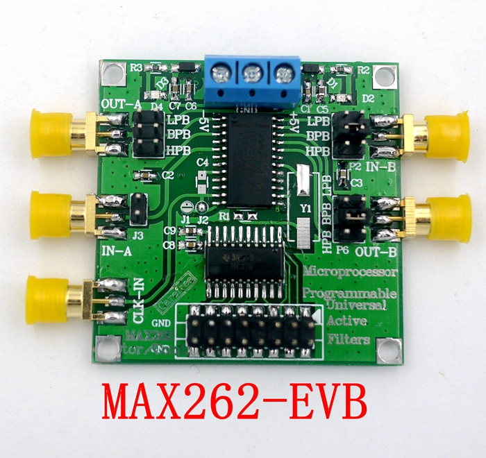
The main chip pin description
V + - positive power input.
V- -Negative power input.
GND - Analog ground.
CLKA - external crystal oscillator and filter A part of the clock input, within the filter, the clock frequency is divided by 2.
CLKB - the clock input to filter B, also within the filter, the clock frequency is divided by 2.
CLKOUT - Clock output for crystal oscillator and R-C oscillation.
OSCOUT - Connects to a crystal or R-C oscillator for self-synchronization.
INA, INB - The signal input of the filter.
BPA, BPB - band-pass filter output.
LPA, LPB - low-pass filter output.
HPA, HPB - high-pass, with resistance, all-pass filter output.
WR - Writing to the active input. When connected to V +, the data can be entered into a programmable memory through the logical interface to complete the filter mode, f0 and Q settings. In addition, it can receive TTL level signals, and the rising edge latch input data.
A0, A1, A2, A3 - address input, can be used to complete the filter mode, f0 and Q of the corresponding settings.
D0, D1 - Data input, can be used to set the corresponding bits f0 and Q.
OP OUT - The amplifier output of the MAX262.
OP IN - The inverting input of the MAX262 amplifier.
Packing list
- Program-controlled filter * 1
5 detail photos · open a photo to swipe through.
No published reviews yet. Share your experience below.
Keep looking
Also in the catalogue.

Set Of 15 Animal Picture Books Featuring Various Animals, For Learning Activities And As A Gift Idea Or Party Accessory Set
$14.99

22-Piece To-Do List Set With 4 Checklist Boards, Pens, And Accessories—Party Supplies Set
$13.99

Foldable Movie Projector Screen 16 To 9 Projection HD Home
$8.99

LCD Charging Small Blackboard Children's Drawing Board Graffiti
$20.99
Find more for “MAX262 Active Filter Module Programmable Filter High Low Pass Bandpass”.
Loading more products…